Injection Molding, The Humble Nozzle Tip
Okay let’s talk about the humble nozzle and nozzle tip. This is your last machine “setting” that you control before the plastic enters the mold. The nozzle and tip are often overlooked when setting up a process.
It’s easy to see the influence that a nozzle or tip can have on a process when you have a process monitoring system with cavity pressure transducers. The process curves below shows 3 different conditions they are; Highest cavity pressure is normal nozzle with GP tip. Second highest cavity pressure was a mixing nozzle with a GP tip. Lowest cavity pressure was a mixing tip. As can clearly be seen the effect on cavity pressure was very significant. This can be a make or break for a process. The other key item to remember in this case is that a change in transfer pressure and cushion were also noted. The transfer pressure and cushion change could be observed by any competent process tech, the advantage of cavity pressure allowed us to see just how much the plastic was impacted. You also may be forced to observe this problem the hard way through increased scrap and process troubleshooting.

The graph below shows the effect on the process that occurred when someone left a 5/32” GP tip on rather than swapping to the required 3/16” GP tip. The dotted lines represent the saved process template with the 3/16” tip and the solid lines were the process curves with the 5/32” tip. The reduction in cavity pressure with smaller orifice tip resulted in a pressure in the cavity of over 25%. 

It is key is to make sure that you develop your process with the correct nozzle and tip and make sure that you always replicate this setup. Things to keep in mind when dealing with nozzles and tips.
1) Keep nozzle length to the minimum required for a given mold. If you don’t have a recessed sprue bushing do you really need a 12” extended nozzle? Each inch of length on the nozzle means more material at temperature and more potential for hot or cold spots on the nozzle. It will also increase the amount of pressure drop between the machine and mold.
2) Ensure that your nozzle heater band covers the length of the nozzle well. Also keep in mind that your nozzle thermocouple may be trying unsuccessfully to control that long length of heater. How confident are you in your temperature control with an extended (12”+) nozzle that has a thermocouple located in the wrench flats? There are better ways to control long nozzles, look for opportunities to get a thermocouple closer to the center of the nozzle. If you have concerns about temperature distribution use a handheld pyrometer to check across the nozzle length (keep in mind this is a rough test but may help identify cold spots).
3) Don’t use a mixing nozzle unless you really need it, these will cause a major pressure drop. If you do use a mixing nozzle make sure the mixing elements are actually in the nozzle.
4) Use the proper size nozzle tip, it should be just smaller than the sprue orifice. If you use too small of a tip opening you will create a pressure drop that could effect your process. Too large and the sprue will stick after the1st shot.
5) Use the required tip style, mixing tips and nylon tips will create restriction that results in pressure drop. Use them where you need them but replace them when they are not needed.
6) With hot runners that have large orifices try to match the nozzle orifice to avoid pressure drops and potential areas of stagnant material sitting just inside the hot runner sprue opening.
Here are some tips to help manage nozzle tips.
1) You can tack weld a 7/8x14 nut on each of your molds so that the specific tip for that mold is threaded onto the nut and follows the mold everywhere. When you change the mold the tip comes off the nut and goes on the press.
2) Grind in identification on your tips and nozzles. This will help give a more visual way of determining what tip or nozzle is on your press. The small stamped letters on tips are very hard to identify once you have some carbon build up on the tip. Grind the i.d. so that it is on more than one side, this will allow it to seen easily from the operator side of the press.

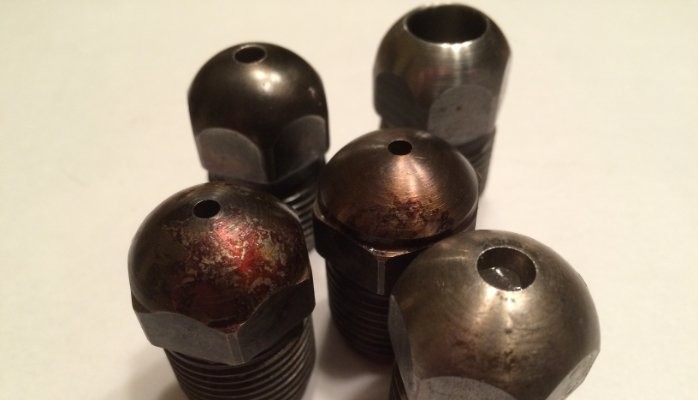
See below for an example of a tip with lines ground in, you could use this to identify full taper tips, grind big “N” for nylon, etc. 
3) Use a tip orifice gage to verify you have the correct orifice for the mold you are working with. Some people are pretty good at eyeballing the tip orifice but why take the chance?
4) It should go without saying but use a 1/2” radius tip with a 1/2” radius sprue and a 3/4” with a 3/4”.
5) Make sure that your setup sheets spell out the length and style of nozzle as well as what type of tip and the required orifice. Once this is documented on your process make sure that you verify that these specifications are being followed.
So in closing please don’t overlook the humble nozzle tip! Easy to ignore but also easy to cause large pressure drop issues. These pressure drop differences can close your process window and lead to scrap. Remember that the little details can ruin your day when processing.
Steve Brammer
Business Development Manager Formerra Distribution
7yGreat article. Would you be willing to send me a copy so I can add it to a design presentation that I have? The nozzle tip becomes an "After Thought" and I am glad that you wrote this.
Advanced Quality Engineer
7yHadn't taken time to post even a few more thoughts... Ensure that Nozzle Touch Pressure always exceeds maximum actual injection pressure (what your process dictates, not necessarily max machine pressure) and that Nozzle Touch Time always exceeds your maximum total injection time (fill and hold times). If too much pressure builds during injection or touch time expires during injection, the injection unit may likely back off, thereby allowing material to ooze between the tip and the sprue bushing. You've seen the results...yet another material cone and possible damage to the tip and bushing. Also, if you must use a sprue break, you will run the risk of drool getting crushed into the sprue. Better off investigating ways to reduce material temp at the tip or add / repair cooling of the sprue bushing to insure a clean break of material after screw charging and decompression. Don't compensate by adding too much suckback or lowering back pressure to minimal amounts. That will result in inconsistent shot sizes, poor material mix with colorants, fillers, etc. , and potentially erratic heating, as mechanical action is reduced which requires heaters to do the work. Not a great plan of attack. Lastly, document these requirements in your validations and on your set-up sheets!!!
Asia Pacific Technical Service Manager
7yHi Steve, do you have a basic illustration of cross section of different type nozzle for each polymer types, I.e., for PC, PA, ABS, etc
Advanced Quality Engineer
7yLike usual, I thought about a few more things after the fact. Not only is it important to have the correct tip each and every time, but it's also important to know the type and location of any heater bands and thermocouples you need. When it's time to replace them, what will you replace with? Was the process validated with a 1 3/4" tip with a 1" x 1.25" 125W heater band? If so, that's what you better use for the repair. I've seen some replace a button tip with a 4 3/4" tip with a 2" 250W heater band. Though the orifice might be the same diameter, you're processing a different animal. Same goes for heater types and thermocouples. Type J or K? Where's it wired to? Nozzle zone or front zone? No guessing allowed. Same for the PID. Unless your machine is dedicated to a specific material, your heater tuning may require some tweaking to ensure stable temp control. This needs to be recorded on your set-up sheet. Like always, it's generally the basics that kill us and cause unnecessary downtime, scrap and unwanted expenses. Take the time to nail it during process development, then document the heck out of it. Take some pictures, too!! They can pay huge dividends in the event of a total catastrophe such as the dreaded material cone mentioned earlier.
Advanced Quality Engineer
7yI fought this battle years ago when wearing my process engineer's hat...not sure why this is still an issue, as everything you mention in your article is spot on and should be clearly understood today by any competent processor. Certainly tip type and size should be documented in any process validation in the event somebody forgets to write it on a set-up sheet. One additional thought to add; when changing a tip make sure your tip and sprue bushing are both clean and undamaged. (This includes the threads on the tip and on the nozzle! And don't forget to install the tip "hot' to correct specs and with the proper amount of anti-seize.) I can't say how many times I've gone out to the shop floor to help with a processing issue only to find a huge material cone bending the heck out of the heat shield and trashing heater bands and thermocouples. The cost of part scrap, equipment repairs and downtime associated with clean up all add up. Make these simple steps everyday practice!